It all began with presentations of various designs and analysis of their up-front costs verses long term savings. Once the final approach was decided on, it was time to put it on paper.

[autocad drawing of the chiller system]
As I began drawing the system the site was being cleared for construction. Due to existing wetlands on the site the building shape and location were revised several times until it produced the least impact on the site.
[Google Earth screen capture]
In early March, 2009, I made a trip to the site:

[From the northeast corner looking to the opposite end of the floor slab 1/4 mile away]

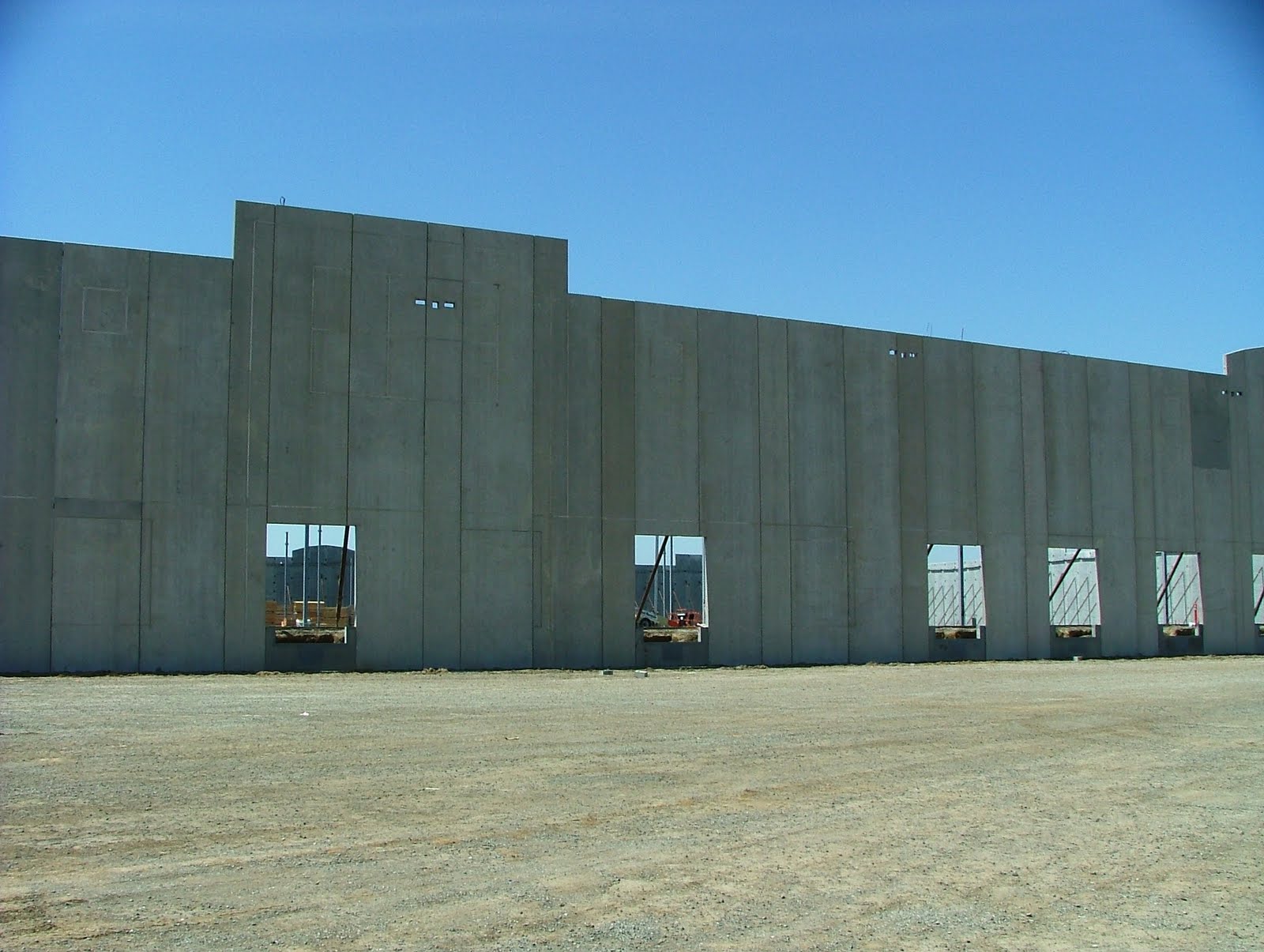
[from the opposite end looking back towards the east end]
I found about one half of the east end wall erected.

The concrete wall slabs were manufactured in Santa Rosa and shipped to the site to save on construction time. Each slab has a number of hollow cores running through it making them much lighter than the poured in place slabs.

[A crane prepares to lift one of the slabs into position]

Upon returning to the site for a meeting exactly four weeks later I was blown away to find the outside walls of the 1300' x 500' building completed.


The following five photos are a sequence of shots of the entire north wall:


Not only was I shocked to find the walls up, but 2/3 of the roof was on also!


The chiller pad with its pumps and evaporative cooling tower begins to take shape. This is the portion of the system depicted in the Autocad drawing at the beginning of this post.


The 500 ton centrifugal chiller. Freon is compressed in the centrifugal turbine and heated in the process due to compression. The hot freon is routed through tubes in the condenser barrel - the lower dome shaped item is the end of this barrel - where the heat is given off to the water which then circulates through the cooling tower to shed the heat. This in turn condenses the freon to a liquid still under high pressure. This liquid freon is then routed to tubes in the evaporator - the end of which is the upper dome shaped object. There it is dispersed through orifices where the resulting pressure drop causes the freon to evaporate to a gaseous state, taking on heat, thereby cooling the water in the evaporator. The chilled water is then circulated through Fan Coils within the building. The 500 ton rating means the chiller is capable of freezing 500 tons of ice in one hour's time. The system produces 1,340 gallons per minute of 35 degree water to feed the building. The first time I heard it start up I didn't know if I should run away or what - not unlike a 747 jet engine coming up to speed!


The completed building and site. To the upper left is the rainwater detention pond, a long narrow area surrounded by levees, only partially filled at this point. It was completed after the rainy season, but in the future will collect all of the rainwater from the site and store it for reuse in irrigating the landscaping. Plants were chosen which are native to the area and require minimal amounts of irrigation. The areas to the right, above the building, are new venal pools, established to replace several which were lost to the construction of the building. These items, along with the air conditioning systems and motion sensors on all of the warehouse lights to keep them off when not needed are what accomplished the LEED Silver Rating. (Animal tracks radiate out from a watering hole on adjacent property next to the vernal pools.)


OMG! Finally you don't have to duck going in the door! :o)
ReplyDeletexoxoxox
LMAO!
ReplyDelete